Floor Slabs
Floor slabs are suitable to bridge larger spans at lesser height of a structure. Betonika UAB, a leading company in the sector of precast concrete element manufacturing, produces floor slabs to individual projects, therefore the architects are provided with greater freedom when designing internal spaces of buildings and preparing layouts of the rooms.
The hollow core slabs are manufactured applying continuous moulding method to the customer‘s layout of the slabs with dimensions of holes, notches, recesses and ties indicated. To produce the slabs, concrete class C35/45 is used. The end edge of slabs can be of a geometric shape indicated in the project (transverse cut, angle must be ≥30°).
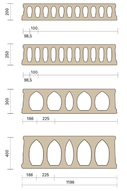
Standard heights of the slabs are 200, 250, 300, 400 mm (HCS200, HCS250, HCS300, HCS400 tipai). Standard width of the slabs is 1200 mm. Manufacture of narrower slabs longitudinally cut every 100 mm is possible, still not narrower than 300 mm (HCS200, HCS250 types) or 360 mm, 600 mm, 720 mm, 960 mm width (HCS300, HCS400 types).
To calculate load bearing capacity of the slabs and select them, a specialized HC-Slab computer program is used. Prestressed reinforced concrete hollow core panels are widely used for prefabricated floor slabs. Their popularity is based on economical cross-section, highly efficient manufacturing method, wide choice of product height and load bearing capacity, smooth underside and structural efficiency.
Precast concrete products are certified at the Construction Products Certification Centres in Lithuania, Belarus and Russia. Certificates of conformity of precast concrete products can be seen here.
Technical Characteristics
Hollow core slabs are manufactured precisely to the dimensions, indicated by the customer.
Table 1 Floor slab parameters
|
Profile |
Width, mm |
Height, mm |
Weight, kg/m2 |
Weight (filled joints), kg/m2 |
Max length of span, m |
|
HCS 200 |
1200 |
200 |
317 |
333 |
9.50 |
|
HCS 250 |
1200 |
250 |
382 |
403 |
12.20 |
|
HCS 300 |
1200 |
300 |
430 |
455 |
14.50 |
|
HCS 400 |
1200 |
400 |
498 |
534 |
16.75 |
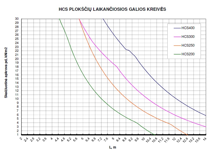
The curves below show change in load bearing capacity of floor slabs depending on span length.

Fig. 1. HSC slab load bearing capacity curves
Notes:
- Assumed estimated loads on a slab pd=gd(45%) + qd(55%);
- Span given (L, m) - "in the light", support length lsup=100mm;
- Weakening of slabs caused by holes shall be evaluated by separate calculations, and is not analyzed here;
- Maximum load bearing capacity curves are presented for each slab profile;
- Slab fire resistance - REI60.
Prestressed reinforced concrete structures have a deflection, the size of which depends on non-centricity of application of prestressed reinforcement tensile strength to the cross-section, cross-section rigidness and length of the element.
Designing requires that deflections of elements should be taken into account foreseeing thicknesses of extra concrete layer and floor levelling layer and final altitudes obtained after works completion, e. g., attention must be paid to proper installation of thresholds.


Fig. 2. Standard slab profiles
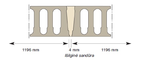
The edges of the slabs are profiled to ensure an even transfer of horizontal and vertical shearing forces to the adjacent elements. The slabs of standard cross-section have fire resistance of 60 to 180 minutes. The 180-minute value is obtained after increase in thickness of the protective concrete layer of prestressed reinforcement bars.
Floor slabs are assembled on the construction site, and usually an extra structural concrete layer is not placed. Still, to withstand dynamic loading or large conentrated loads, an extra upper concrete layer may be required, the thickness of which is not less than 40 mm, while concrete class - C30/37. A monolithic concrete layer must be installed immediately after joint filling.
Openings and Cuts in Hollow Core Slabs
Openings and cuts are made on the centreline of cores. Maximum size shall not be greater than width of the core. Openings and cuts are made during manufacturing process. The edges of the openings and cuts are coarse.
Table 2 Maximum dimensions of opening or cut
|
l/b |
HCS 200 - 250 |
HCS 300 - 400 |
|
Angular cut (1) End cut (2) Edges (3) |
1200 / 600 1200 / 600 1200 / 600 |
1200 / 600 720 / 600 1200 / 600 |
|
Circular opening (4) Rectangular opening (4) |
Ø 50 1200 / 600 |
Ø 135 960 / 480 |

Fig. 3. Openings and cuts in hollow-core slabs
Storage and Transport
Allowable tolerances of a product can slightly increase the weight of a production item. You must not forget that when selecting a crane it is necessary to take into account not only its lifting capacity and production item weight, but also the self-weight of the lifting facility. Floor slabs are hoisted using special grippers with a distributing traverse. It is forbidden to use only straps. Lifting facility (a traverse with grippers) shall be recommended and rented by the manufacturer of floor slabs, after and agreement has been entered into.
Intermediate storage on the construction site usually is not necessary, because production items are erected directly from the truck. If the intermediate storage is necessary, the site must be levelled horizontally in advance. The slabs are stored on semi-soft (e. g., wooden) battens, which are placed under the ends of the slab. When stacking precast concrete production items, the battens must be in one line above each other. The base must be solid and firm, while position of the battens must be horizontal so that additional forces and tension will not occur due to setting of a temporary propping device. When hoisting the slabs, all necessary precaution measures must be taken. For example, protective chains must be used.
Floor Slab Assembling
The hollow core slabs are assembled in accordance with the project. Betonika UAB provides Recommendations for Floor Slab Assembling.
Table 3 Maximum length of support of hollow core slabs (loosely resting).
|
Support base |
Slab thickness |
Support length a |
|
|
Maximum length |
Minimum effective length |
||
|
Concrete or metal |
≤ 250 mm ≥ 300 mm |
70 mm 100 mm |
50 mm 80 mm |
|
Masonry |
≤ 250 mm ≥ 300 mm |
100 mm 120 mm |
80 mm 100 mm |

Fig. 4. Neoprene tapes ensure even distribution of the load.
